EPAS Harness#
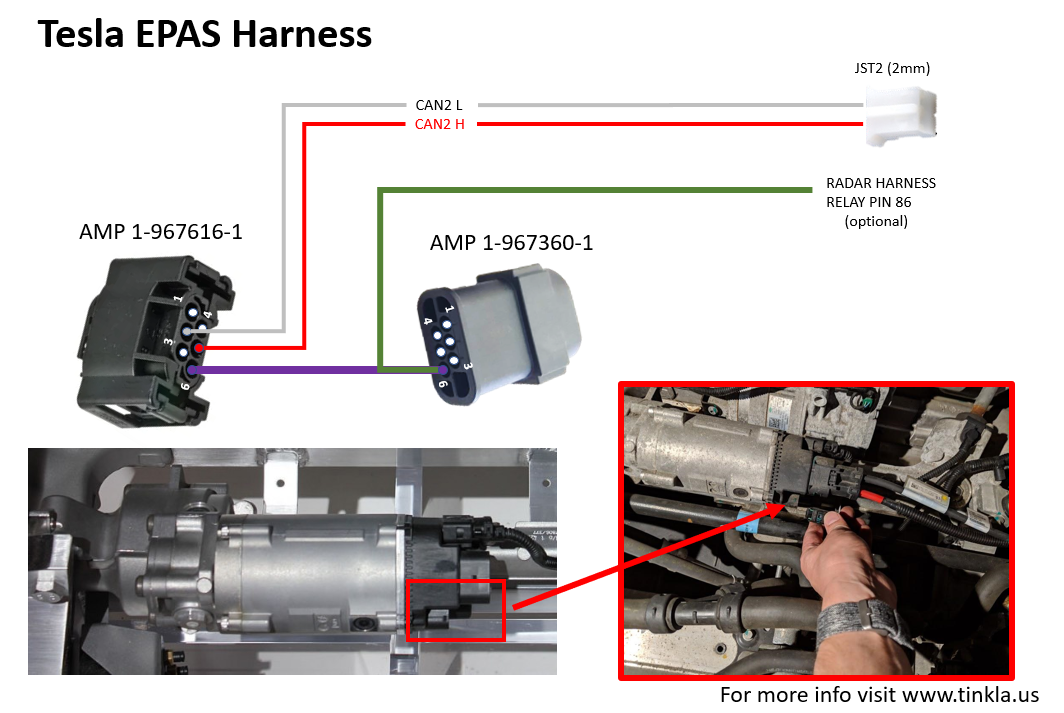
The EPAS harness connects the Electric Power Assisted Steering (EPAS) servo unit to your OBD-C Adapter, allowing openpilot to send steering commands on preAP Model S vehicles. This is a DIY harness that you build and install yourself.
Parts#
All connectors are available from Mouser:
| Part | Mouser PN |
|---|---|
| Female connector | 571-1-967616-1 |
| Female pins | 571-5-962885-1-LP |
| Male connector | 571-1-967587-3 |
| Male pins | 571-1-928918-1-CT |
| Rubber seal plug | 571-967067-1 |
| Rubber seal for cable | 571-967056-1 |
You also need a length of two-conductor shielded cable to run from the EPAS servo (under the hood) to the OBD2 port area (driver footwell).
Build Guides#
- Putting together a Tesla EPAS wire harness by @Raf & @erflesby
- @Raf’s Installing EPAS cable guide in pictures
Installation Tips#
Routing the cable#
- Start at the EPAS servo under the hood. Use velcro ties to temporarily secure the cable to the existing harness — don’t permanently fasten anything until you’ve confirmed everything works.
- Fish the unfinished end of the cable under the washer fluid container, through the first hood metal support piece, and into the gap.
- Pull all slack through, then reinsert the cable end back into the gap. Use a finger or screwdriver underneath to keep the cable from falling flat — this prevents it from catching on the second metal hood support.
- Push the cable towards the cabin. Once it emerges next to the door seal, pull it through from the cabin side.
- Work it behind the seal and down to the area near the OBD2 port in the driver footwell.
Do not solder the JST2 connectors before routing the cable. The fishing process can easily break solder joints. Route the wire first, then strip and solder the connections once the cable is in place.
Testing before connecting#
Before plugging anything in, test your cable for continuity and shorts:
- Shorts: With the cable disconnected from both ends, insert spare pins into positions 2 and 5. Touch your multimeter leads to them — you should get no continuity. If you do, check that the pins aren’t touching each other, and inspect your solder joints for bridging.
- Continuity: With spare pins still in 2 and 5, jumper the two wires together at the JST2 end. Touch your multimeter leads to pins 2 and 5 — you should get continuity. If not, check your solder connections.
Connecting to the car#
- Plug the EPAS connector end into the EPAS servo unit under the hood.
- Plug the JST2 end into your OBD-C Adapter in the footwell.
- If you get a “Power Assist is not available” error, your CAN +/- wires (pins 2 and 5) are swapped. Swap them at the JST2 connector by lifting the plastic lock tab, releasing the pins, and reinserting them in the opposite positions. Put the car in Drive and verify that power steering feels normal — the error should clear.